Modification of La Spaziale S1 (Mini) Vivaldi II with timer, web interface, manual dose, power meter and printserver with airprint: Unterschied zwischen den Versionen
JoPa (Diskussion | Beiträge) |
JoPa (Diskussion | Beiträge) |
||
| Zeile 365: | Zeile 365: | ||
If everything works you have done it and the housing can be closed. | If everything works you have done it and the housing can be closed. | ||
| − | == Others == | + | == '''Others''' == |
Powered by web interface | Powered by web interface | ||
Version vom 9. November 2015, 19:30 Uhr
Information
Due to requests from english users, this page will become the english translation of the german documentation: https://www.kaffeewiki.de/index.php?title=Umr%C3%BCsten_der_La_Spaziale_S1_%28Mini%29_Vivaldi_II_auf_Timer,_Webinterface,_manuellen_Bezug_und_Stromz%C3%A4hler
As a start this will be the transpation via google translate. Everybody is invited to improve this page and do a better translation.
Installation of a timer "Vivaldi myTimer" in the Vivaldi incl. WLAN / WiFi
Aditionally the installation of further options will be described.
The following options are installed independent of the timer. But it is mostly so little additional effort, so it is advisable to implement this, when the machine is opened.
Option 1: Switching automatic load / manual draft
option 2: energy meter
Option 3: Shot timer incl. shot administration
Option 4: automatic backflush
Option 5: boiler shutdown (not in mini Vivaldi)
Project description
By installing a single-board computer (Raspberry Pi) into the Vivaldi a week clock timer with unlimited switching times will be realized.
As an additional feature the Vivaldi will get a wireless lan and can be switched on and off via PC/tablet and smartphone. In addition, the timer can be programmed web-based. By usage of relays keypresses to the power putton will be simulated by the Raspberry.
The material costs are about 65,- US$.
Functions
- Programming the (mini) Vivaldi wia web interfache
- Unlimited amount of timers to switch on/off the machine (daily, weekly, individually switchable) (with/without steam boiler in the non-mini)
- Switching on/off via web interface with popular browsers (eg with a smartphone when you are out)
- The non-Mini can be switched on with without steam boiler via the GUI optional
- Power on / off by building control via web Interface
- Automatic and manual shot Timer
- Shot administration (database with comment and favorites function) (Shots under 8 seconds will not be saved)
- The shot database can be cleaned by pressing a single button (all uncommented entries without favourite flag and without mark)
- all timers can be programmed individually with/without switching steam boiler shutdown (Not for mini Vivaldi)
- automatic shot can be switched off (manual draft)
- backflush automatic
- electric meter incl. electric cost calculator
- user management with authorisation concept
- configuration completely possible through the graphical interface
- phpMyAdmin can be used for data migration
- configuration of WLAN on Windows directly to the SD card possible
- integrated printserver with airprint
Screenshots
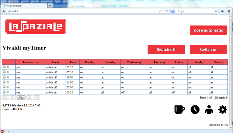
The web interface is available from PC / tablet or smartphone via web browser.
The timer includes manual on / off and change the automatic / manual dose.
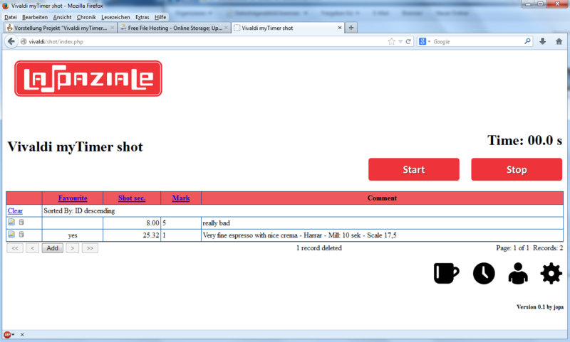
shot timer / shot administrative
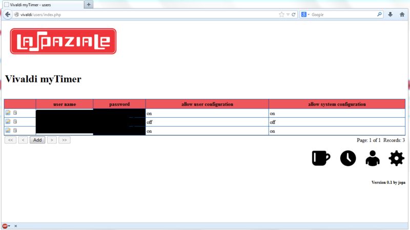
user management
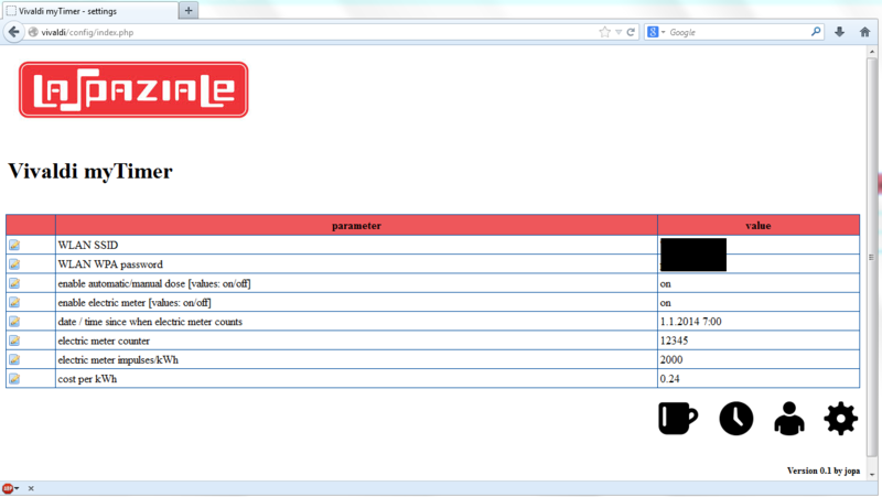
configuration
Security note
The tasks described here may only be carried out by competent persons. When working on high voltage (120V/230V) can be deadly. Moreover, in case of errors the machine may be damaged.
Disclaimer
This description portrays the modification of my machine. There is no guarantee that errors have crept in. For this reason, do not accept all descriptions 1 : 1. It is intended primarily to be able to understand the work and to pay an own modification without this description. I am not responsible for any damage! This description is an initial draft. It would be glad if someone would check the description is correct. Suggestions, corrections and additional photos are welcome.
The material
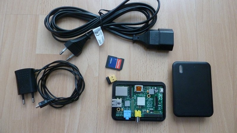
The Raspberry PI (Rev. 2), a housing, a 4GB SD card, a WLAN stick, an AC adapter and an extension to realize a socket inside the Vivaldi for the power adapter. Who mounts the Raspberry externally, can also operate with a standard electrical outlet.
Note: The Raspberry PI (Rev. 2) is not 100% compatible with the Rev. 1. Due to the modified connector strip is not running the software provided correct.
Raspberry PI B + is pin-compatible and can therefore be used.
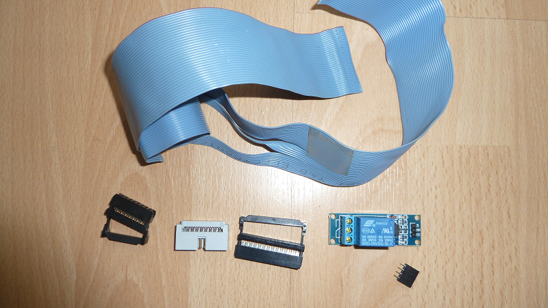
The cable and a relay.
The components can be bougt at Reichelt: here the shopping chart
Then we need a the relay board with one or two relays. Here helps ebay search for "relays raspberry". Screws on both sides avoid soldering.
For option 2, a elecric meter is required. Ebay search for "electricity meter S0" will show some. There are models with different pulses per kW. The higher the value, the more accurate the count. 1000 pulses are but adequate.
The software
The software is available here (2-3GB): Download
Currently a password will be needed to unpack.
The password will be sent via PM after downloading. For this I need the user from KaffeNetz or from S1Cafe. In both of these forums I will support myTimer. To other mail address I will not send messages.
German support is provided here: [1]
English support page is here: [2]
Here is an example of the surface through the browser of an iPhone:
Datei:VivaldiMyTimer iphone.png
Installation
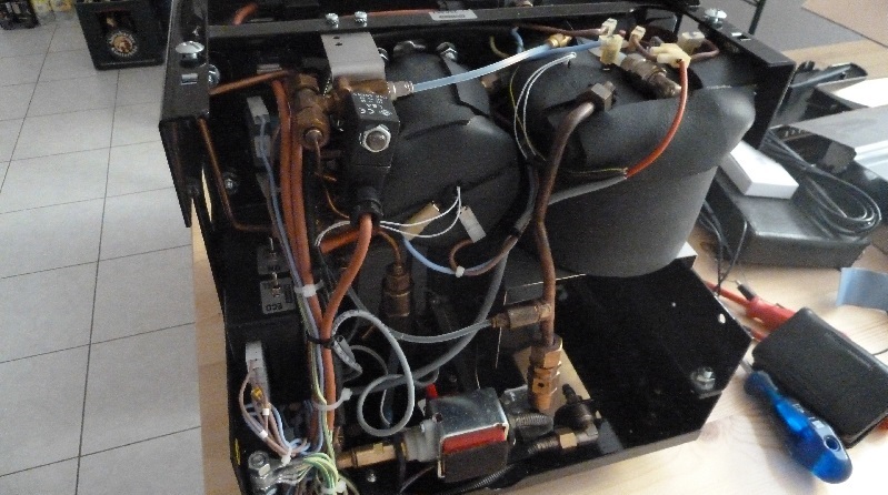
In my Vivaldi I mounted the Raspberry inside the machine. For temperature reasons i can only recommend this of the boilers are isolated. For uninsulated kettles I recommend to put back to the Vivaldi the Raspberry. But if the machine is open anyway, an insulation with Armaflex is done but also fast.
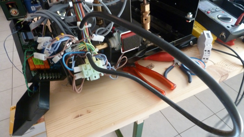
1. First, the machine must be opened:
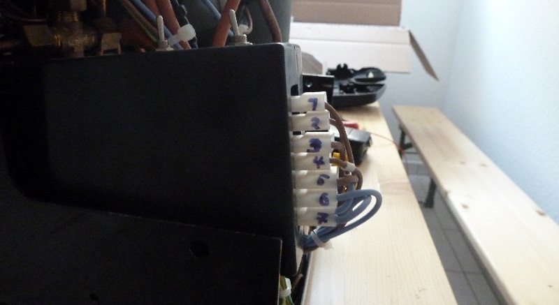
2. Connect the cable from the control unit to control electronics should be made clear so that the control electronics can be pulled to the rear:
3. The plugs should be labeled so that they too will find the right place on the control electronics.
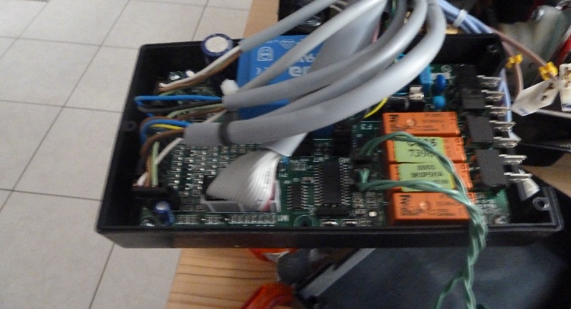
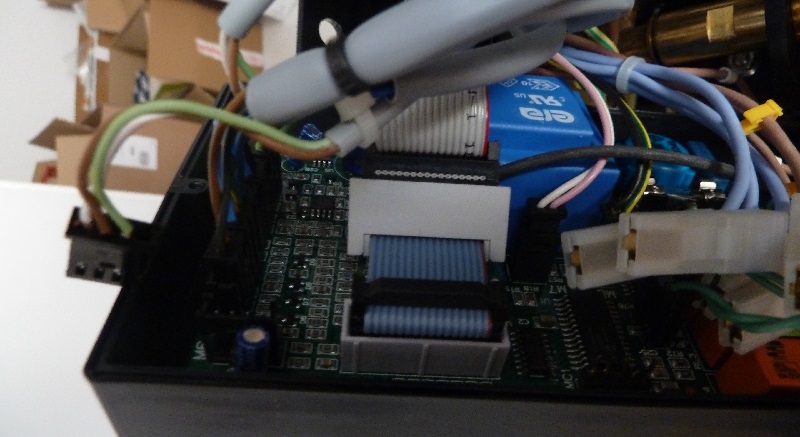
4. Open the box of the control electronics:
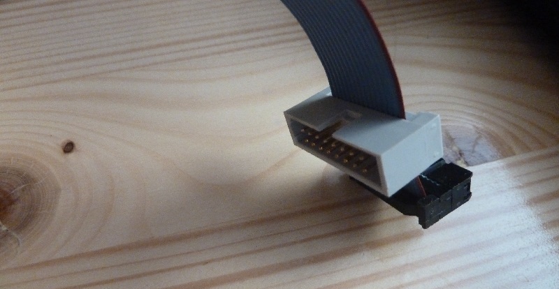
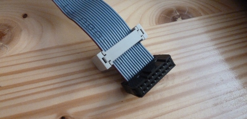
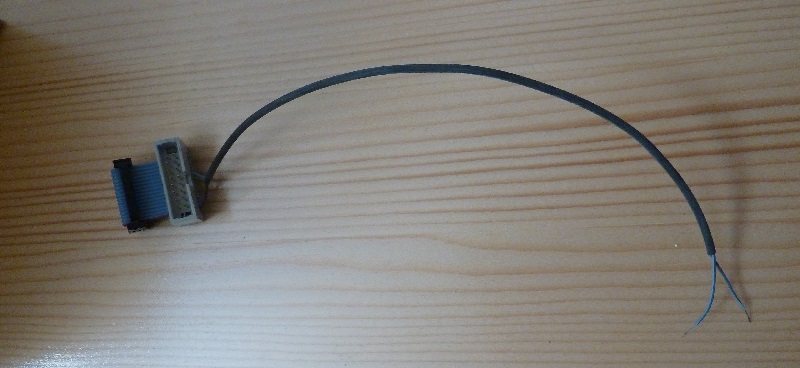
5. By means of an adapter cable, we dress the necessary pins out.
Important here is the direction of the markings.
The nose of the female connector and the recess of the plug strip facing upwards!
6. We need only the veins 1 (red) and 11 for the relay on / off. For the "backwash" option we need the wires 2 and 7 (7 is the double reference, 2 and 5 (single reference) would go). For the "Boilerabschakltung" option we need the wires 2 and 9. FIG.
All other we remove. The two veins we are stuck in a shrink tube.
7. Insert adapter cable.
8. Option 1:
Preparing for automatic load detection (only necessary if this function is desired)
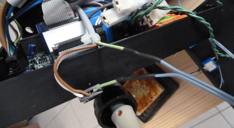
For this purpose, the plug next to the ribbon cable is severed and lengthened the green wire, so that it can be connected later on our relays:
9. Now the cable between relay and Raspberry is assembled.
I chose solder connections. But there are also a number of relays with screw manufacturers. So then no soldering would be necessary during the conversion.
On the relay boards, the connections are usually labeled well.
On Raspberry we use the following pins:
For the timer
Raspberry Pin2 (+ 5V) ---> VCC relays
Raspberry Pin 14 (ground) ---> relays GND
Raspberry Pin 15 (Gpio22) ---> relays
Option 1: Switching automatic load / reference manual
This option is recommended. We only need another artery and a relay board with two relay only costs about 1, - EUR more than the board with only one relay.
Raspberry Pin 16 (Gpio23) ---> Relay2 IN
Option 2: Energy Meter
As a second function, a power meter to be installed. It sends each consumed kWh depending on the model 1000 or 2000 pulses to the Raspberry.
These pulses we can evaluate and let the consumption and the kWh-price costs Show.
For the meter about 20, - US$
Raspberry Pin 5 (Gpio03) ---> meter S0 +
Raspberry pin 6 (ground) ---> meter S0 -
Option 3:. shot timer incl. shot administration
A relay in parallel with the solenoid valve provides us with the necessary contact.
PINs:
Raspberry Pin 3 (Gpio02) ---> RELAY5 closers
Raspberry pin 6 (ground) ---> RELAY5 NO (PIN same as in option 2)
Option 4: back flush automatic
Raspberry Pin2 (+ 5V) ---> Relay3 VCC
Raspberry Pin 14 (ground) ---> GND Relay3
Raspberry Pin 18 (Gpio24) ---> Relay3 IN
The NO contact of the relay goes to the control panel wires 2 and 7.
Option 5: Boiler shutdown
Raspberry Pin2 (+ 5V) ---> Relay4 VCC
Raspberry Pin 14 (ground) ---> GND Relay4
Raspberry Pin 22 (GPIO25) ---> Relay4 IN
The NO contact of the relay goes to the control panel wires 2 and 9.
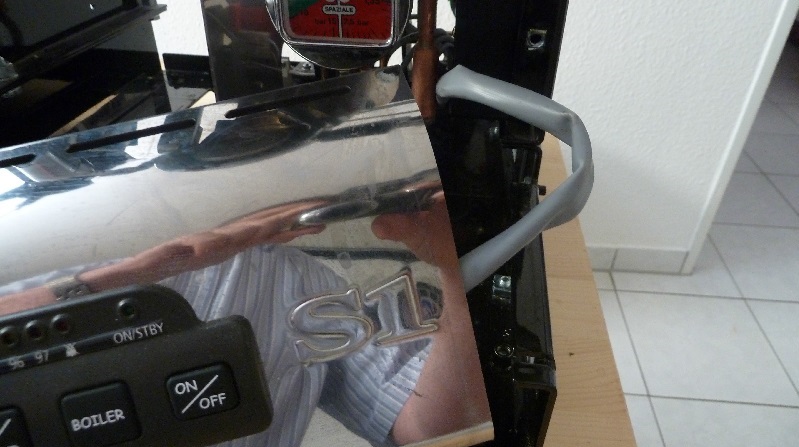
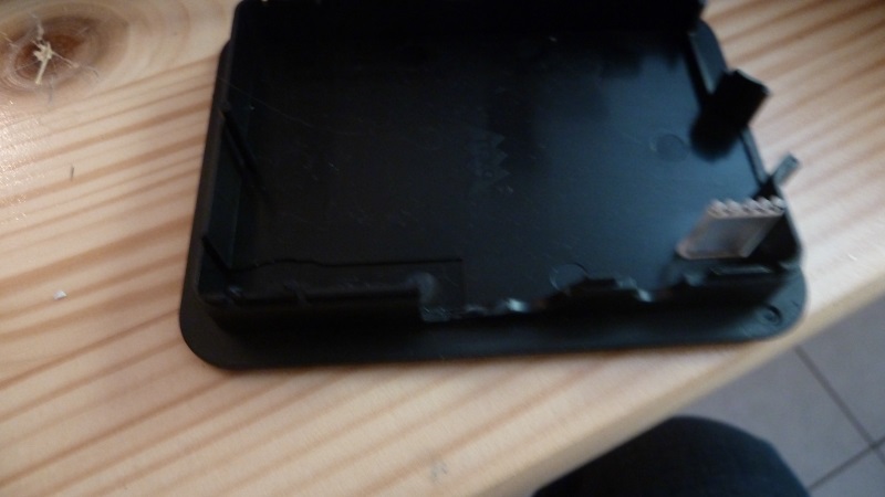
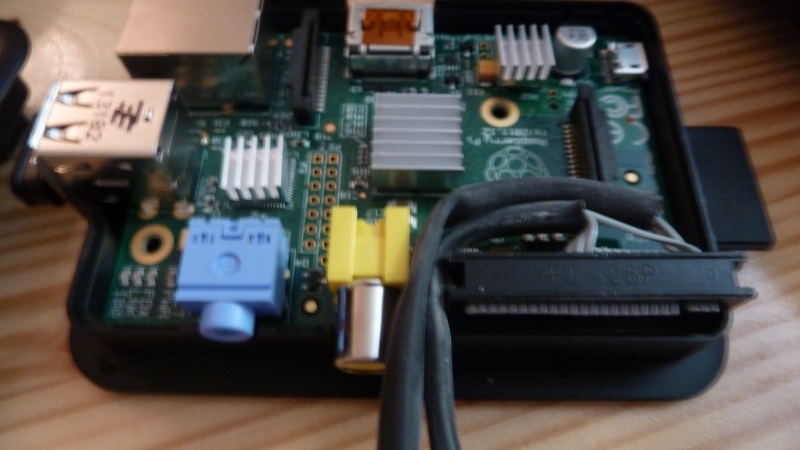
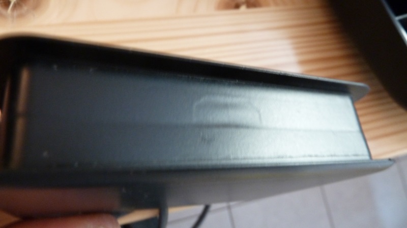
10. For the cables we need a recess on the housing.
I have this extended directly to the female RCA connector and then pulled through the cable.
11. The sealed casing can be protected with an insulating anything against any moisture.
(Due to the many holes on the chassis that's more of an alibi work;))
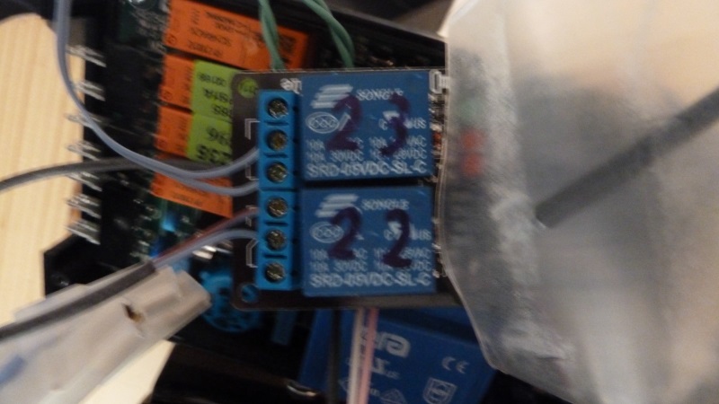
12. Connection of the relay board
GPIO22 turns the machine on and off.
The two cables from the adapter cable to the control unit come on normally.
GPIO23 switches the automatic load.
The two extended cores of the green terminal come on the opener.
The connection diagram can be seen in the photo below the veins.
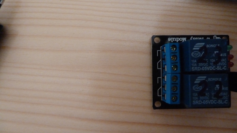
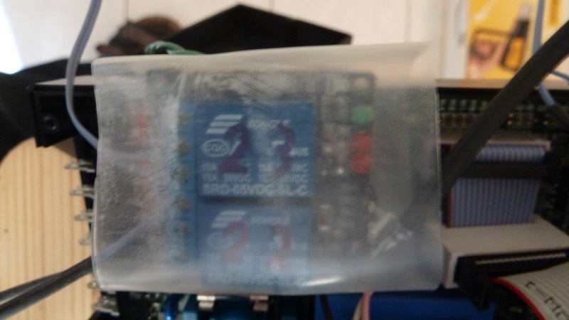
Here is a photo of the not connected relays.
Who renounces the option 1 (automatic load detection) of course has only one relay.
Anyone who uses three relays, is prepared for the coming option "automatic cleaning program".
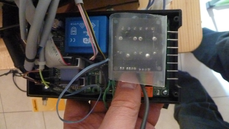
13. The completed attached relay should be protected against short circuits, as we put it in with the casing of the control electronics.
I have used a shrink tube. Wrap with electrical tape should also rich.
14. Here there is still space for our relays.
Now the housing of the control unit can be closed again.
15. Now only missing the Stomanschluß for our Raspberry.
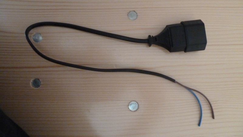
For this we cut out the extension simply the clutch off and connect it to the power cord of Vivaldi.
16. Option 2: electricity meter (only if necessary)
Now can also be installed easily the electricity meter.
Just the power cord of Vivaldi pull something into the machine until it reaches to the cup warmer.
The cables at the top of separation and use the electricity meter.
L is the brown wire direction outlet.
N the blue wire towards outlet.
The outputs are labeled accordingly.
S0 + goes to Raspberry Pin5 (GPIO3).
S0 + goes to Raspberry Pin6 (mass).
If the electricity meter as a display my have, so must not be visible, as we read the values on the Raspberry.
17. Option 3: Shot Timer (only if desired)
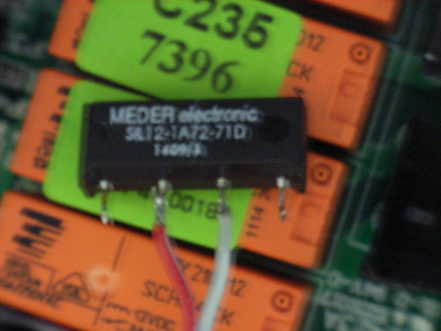
We engage the shot timer from the relay for the solenoid valve. Obtain Due to the size and a potential free contact, I have used a reed relay with built-in freewheeling diode.
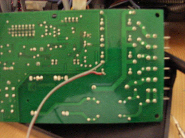
The solder points on which we can solder the relay we see in the following image. !! Caution !! Unfortunately, the cores (+/-) are reversed on the photo. After correction I forgot to make a new image.
And here the used reed relays. That there are also favorable at Reichelt (SIL No. 7271-D 12V). The designation reads: SA12-1A72-71D
18. Now everything can be reassembled.
The Raspberry I tucked in my top of the cup warmer.
The SD card is facing up, so I can easily make a firmware change.
With cable ties of the ammeter and the Raspberry can be fixed.
19. Now we need the software. The Image I'll put here on the board are available. Link follows.
With the tool "Win32 Disk Imager" it is written to the SD card.
Then plug in the Raspberry and connect via cable to the network.
Now the plug into the socket of Vivaldi.
After 2 minutes, the web interface should be under http: // Vivaldi / be accessible.
The login is: viv
Password: viv
Now a test of the correct wiring of the relay can be carried out.
20. In the "Settings" menu, which is accessible through the gear icon at the bottom right, the system settings can be made.
Here, the SSID and the WAP-Key of the WLAN network is entered. Then the power plug (power) must be taken shortly and the LAN cables are pulled.
Insert power plug.
After 2 minutes, the web interface should be accessible via WLAN.
Note: Probably only WPA2 works without problems.
Possibly there are also some special characters in the WPA Key problems.
If everything works you have done it and the housing can be closed.
Others
Powered by web interface
Here the possibility the Vivaldi to switch directly over web interface.
This can be used for various automation. eg FHEM
Switching on: http: // username: password@vivaldi/gpio_on.php
Off: http: // username: password@vivaldi/gpio_off.php
Time Zone
A hint for my non German users: You will have a timezone problem, Because The image is configured to German timezone. It is easy to change this via console:
To change timezone, please use the program Putty to enter the shell of the raspberry. User: pi Password: Vivaldi
Use "sudo Raspi-config" to change timezone.
printserver
You can configure the build in printserver with: http://vivaldi:631
